TLDR:
SYSCONFIG SDM_PORT=PROGRAMN SLAVE_SPI_PORT=ENABLE; to your .lpf file.Bugblat does not longer list the resources for the original PIF on their site. They can be found here:
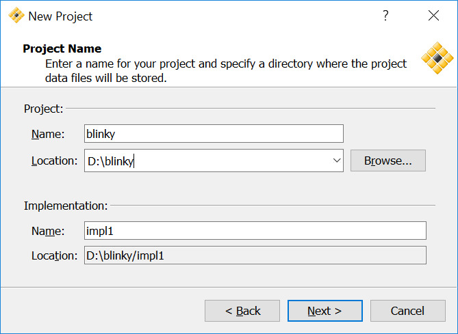
Create a new project:
First of all we will locate the $ProjectName.lpf file and add the line
SYSCONFIG JTAG_PORT=DISABLE SDM_PORT=PROGRAMN I2C_PORT=DISABLE SLAVE_SPI_PORT=ENABLE;
Therefore we wont lock ourself out of I2C->SPI flashing.
Now add a VHDL file to the project:
LIBRARY ieee;
USE ieee.std_logic_1164.all;

ENTITY blinking_led IS
   PORT(
      LEDR : OUT STD_LOGIC;
      LEDG : OUT STD_LOGIC
      );
END blinking_led;

ARCHITECTURE behavior OF blinking_led IS
   SIGNAL clk  : STD_LOGIC;
   SIGNAL led : STD_LOGIC;
   --oscillator
   COMPONENT OSCH
      GENERIC(
            NOM_FREQ: string := "53.20");
      PORT(
            STDBY    : IN  STD_LOGIC;
            OSC      : OUT STD_LOGIC;
            SEDSTDBY : OUT STD_LOGIC);
   END COMPONENT;
BEGIN
   --oscillator
   OSCInst0: OSCH
       GENERIC MAP (NOM_FREQ  => "133.00")
       PORT MAP (STDBY => '0', OSC => clk, SEDSTDBY => OPEN);
   PROCESS(clk)
        CONSTANT LIMIT : INTEGER := 10000000;
        VARIABLE count : INTEGER RANGE 0 TO LIMIT;
    BEGIN
      IF rising_edge(clk) THEN
         IF(count < LIMIT) THEN
            count := count + 1;
         ELSE
            count := 0;
            led <= NOT led;
         END IF;
      END IF;
    END PROCESS;
    LEDG <= NOT led;
    LEDR <= led;
END behavior;
Next we need to map LEDR and LEDG to the board pins. Therefore we add to our projects .lpf file:
LOCATE COMP "LEDR" SITE "112" ;
LOCATE COMP "LEDG" SITE "113" ;

IOBUF PORT "LEDR" IO_TYPE=LVCMOS33 PULLMODE=DOWN ;
IOBUF PORT "LEDG" IO_TYPE=LVCMOS33 PULLMODE=DOWN ;
On the left in the process tab we can now choose JEDEC File and use a Doubleclick on that target to synthesize.
Find the .jed file in your implementation folder and copy it over to your raspberry pi, where you can flash via:
sudo python pif/software/pifload.py blinky_impl1.jed
assuming your file is called blinky_impl1.jed.
====================hello==========================
Configuration file is fpga/blinky_impl1.jed
Using pif library version: 'libpif,Nov 18 2017,22:23:31'

XO2 Device ID: 012bd043  - device is an XO2-7000HC
XO2 Trace ID : 00.44.30.77_87.20.30.2B
XO2 usercode from Flash:  00.00.00.00
XO2 usercode from SRAM :  00.00.00.00
JEDEC file is fpga/blinky_impl1.jed
starting to read JEDEC file
first configuration data line: 21
. . . . . .
last configuration data line: 1586
1566 frames
finished reading JEDEC file
erasing configuration flash ...  erased
programming configuration flash ...  . . . . . . . . . . . . . . . . . . . . . . . . . . . . . . . . . . . . . . . . . . . . . . . . . . . . . . . . . . . . . . . programmed
transferring ...
configuration finished.

==================== bye ==========================
You should now have a led blinking pif board.
If you don’t sythesize with SDM_PORT=PROGRAMN SLAVE_SPI_PORT=ENABLE the PIF will no longer respond to your flashing attemps.
This is noticeable by the reported IDs beeing all zero.
$ sudo python pif/software/pifload.py pif/firmware/7000/flasher/syn/pif_flasher.jed
====================hello==========================
Configuration file is pif/firmware/7000/flasher/syn/pif_flasher.jed
Using pif library version: 'libpif,Nov 18 2017,22:23:31'

XO2 Device ID: 00000000  - unrecognised ID!
XO2 Trace ID : 00.00.00.00_00.00.00.00
XO2 usercode from Flash:  00.00.00.00
XO2 usercode from SRAM :  00.00.00.00
JEDEC file is fpga/blinky_impl1.jed
starting to read JEDEC file
JEDEC file does not match FPGA

  FPGA is XO2-256HC

  JEDEC identifies as "NOTE DEVICE NAME:        LCMXO2-7000HC-5TQFP144*"

==================== bye ==========================
Bugblat added a reset test pad that can be used to bring the PIF back up.
Connect the testpad to GND and recover by flashing the default firmware:
sudo python pif/software/pifload.py pif/firmware/$VERSION$/flasher/syn/pif_flasher.jed
Replace $VERSION$ either with 7000 or with 1200 based on your hardware.